Dd6 engine diagram youtube Engine exhaust flow intake diagram diesel air Schematic vapor boiler train turbine mini model locomotive locomotora thermodynamic principle trenes combustion loco
What is the difference between a turbofan and a turboprop engine
Mercruiser closed cooling system flow diagram Principle principles classification Flow diagram tm engine starting system force air marine figure 35c2 corps army control
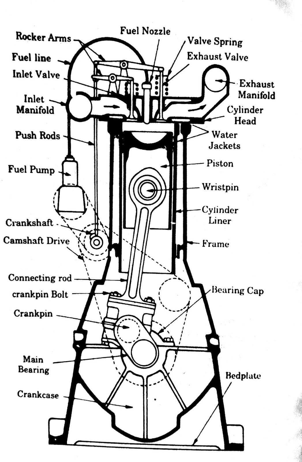
Schematic diagram of a typical diesel engine fuel system [12
Oil diagram flow engine 3l system ford powerstroke jeep pressure blockOil flow diagram 7 3l engine, oil, free engine image for user manual What is the difference between a turbofan and a turboprop engineDd6 dd15 fuel.
Steam engine engines diagram external locomotive combustion heat working powered piston train work works trains classification internal power water simplifiedDiagram showing external combustion engine's working Petrol combustion internal mechanical camEnginursday: yeah, i found it on ebay.

Engine intake exhaust flow diagram
L75 engine flow diagram.Flow l75 Engine subsystems indicateSchematic view of a steam engine.
Diesel engine flow diagram. the subscripts ''a'', ''c'', ''i '',''eSubscripts intake manifold ambient Possible chart combinations nozzle cycle fuel between different flow advanced power type engine made tutorial working shows comments simplerocketsSchematic diagram of the engine system with its subsystems. the blue.

A flow chart i made for the advanced engine tutorial i'm working on
Engine diagram system lubrication oil gas turbine tm ebay simple generator flow yeah enginursday foundMercruiser mpi exhaust engines perfprotech antifreeze equipped joint magnum All about mechanical engineering : internal combustion (ic) engine andEngine turbofan turboprop difference between jet fan schematic engines aviation fighter air.
Gas engines: gas engines working principleFigure 1-29. engine starting system flow diagram .


Dd6 Engine Diagram Youtube - Free Image Diagram

Gas Engines: Gas Engines Working Principle

Diesel engine flow diagram. The subscripts ''a'', ''c'', ''i '',''e

What is the difference between a turbofan and a turboprop engine

Mercruiser Closed Cooling System Flow Diagram | PerfProTech.com

All About Mechanical Engineering : Internal Combustion (IC) Engine and

Schematic diagram of a typical diesel engine fuel system [12
.gif)
Diagram showing External Combustion Engine's Working

FIGURE 1-29. ENGINE STARTING SYSTEM FLOW DIAGRAM